JA-183M
Service explanation for JA-183M
Wireless magnetic contact
The JA-183M detector is part of the Jablotron 100 series alarm system. It ensures the detection of the opening of a door, window and the like. The detector communicates wirelessly and is battery powered.
Installation
The product must be installed by a trained technician with a valid Jablotron certificate.
Choose a suitable place for installation. The detector responds to increasing the distance from the magnet. The transmitter part is mounted on the fixed part of the door (window) and the magnet on the moving part. Avoid placing directly on metal parts (they will negatively affect the operation of the magnetic sensor and radio communication).
1. Open the detector's shield (by pressing the plunge clip, see Figure 1).

Image 1 and 2
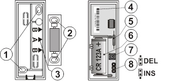
2. Screw the plastic back panel onto the fixed part of the door (window). Signs A,B on this back wall indicate the location of the magnet (image 3).

Figure 3 and 4 - 1. mounting holes for mounting the transmitter; 2. mounting holes for fixing magnet A, 3. position of magnet A,B; 4. serial number; 5. contact tab; 6. battery CR123A; 7. tamper switch; 8. reaction setting
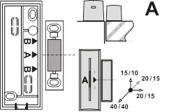
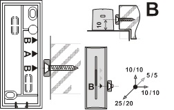
3. Screw the magnet onto the moving part of the door (window). Place the magnet in the plastic case with the center of the case against the A arrow, the ring magnet must be opposite the B arrow. The distance of the magnet from the transmitting part must be as short as possible when the door is closed. The distances for activation when increasing the distance of the magnet over all axes and for non-magnetic / magnetic mounting base are indicated in figures 5 and 6. Note. Use the supplied washer to adjust the height of the A magnet.


Image 5 and 6
4. Learn the detector in the control panel (receiver). Follow the manual of the control panel (receiver). The learning signal is sent when the battery is connected. Note. If you are learning the detector in the receiver after the battery was already connected, first disconnect it, then press and release the screen contact (the residual energy will be used up) and only then execute the learning mode.
5. Set up the detector's functions - see Setup
6. Place the transmitting part on the plastic back wall and click it in.
7. Test whether the detector works reliably.
8. The plunge clamp can be locked with the supplied screw (image 2).
Institution
Jumper INS / DEL (Error! Source of links not found.) determines whether the detector is on the access road to the house and provides an exit and entry delay = position DEL. Conversely, position INS means immediate response from the system. Note: This setting is only meaningful when used with the Jablotron control panel with set response NATUR. If a different reaction has been set in the detector's control panel, or you are using the detector with a JA-182N or JA-180N receiver, the switch setting has no meaning.
The detector has two operating modes, indicated by one or two flashes of the indicator light when the battery is inserted.
One flash means that the detector reports opening and closing to the system. In this way, the status of the window or door can be followed. Two flashes mean that the detector only reacts when it opens (increasing the distance of the magnet).
To switch modes, press and hold the screen's protective contact switch, insert the battery, and release the switch 3-5 seconds after inserting the battery. The detector will then flash once or twice, depending on the mode just selected.
Detector testing
For 15 minutes after closing the screen, the detector indicates activation by means of the signal light. The control panel can check the detector signal in service mode, including measuring the signal quality.
Replace battery in detector
The system checks the battery status and as soon as it starts to run low, informs the user (possibly also the service technician) via the system's communicator. The detector continues to operate and also indicates any activation with a short flash of the light. We recommend replacing the battery within 2 weeks. The battery is replaced by the technician in service mode. Test the operation of the detector after replacing the battery.
If a weak battery is inserted in the detector, its signal light will flash for approx. 1 minute. After that, the detector will work, but will report a low battery
Note: Do not dispose of a used battery with household waste, but dispose of it with chemical waste.
Remove detector from system
The system reports any loss of the detector. If you intentionally disassemble the detector, you must also delete it in the control panel.
Technical parameters
Power supply lithium battery type CR-123A (3.0V 1.5 Ah)
Typical battery life approx. 3 years (max. 20 activations/day)
Communication band 868.1 MHz, Jablotron protocol
Communication range approx. 300m (direct visibility)
Typical break/make distance image 5 a 6
Dimensions transmitting part 75 x 31 x 23 mm
magnet A: 56 x 16 x 15 mm, magnet B: Ø10 x 4 mm
Environment according to EN 50131-1 II. inside, general
Operating temperature range -10 to +40 °C
Classification grade 2
in accordance with EN 50131-1,EN 50131-2-6, EN 50131-5-3
Further complies with ETSI EN 300220, EN 50130-4,
EN 55022, EN 60950-1
The detector is designed and manufactured in accordance with the applicable provisions: Government Decree No. 426/2000 Coll., provided that it is used according to its intended purpose. Original Declaration of Conformity can be found on www.jablotron.cz in the Advice (Support) section.
Note: Although this product does not contain any harmful materials, do not dispose of it with household waste, but hand it in at the collection point designated for electronic waste.
Installation
The product must be installed by a trained technician with a valid Jablotron certificate.
Choose a suitable place for installation. The detector responds to increasing the distance from the magnet. The transmitter part is mounted on the fixed part of the door (window) and the magnet on the moving part. Avoid placing directly on metal parts (they will negatively affect the operation of the magnetic sensor and radio communication).
1. Open the detector's shield (by pressing the plunge clip, see Figure 1).

Image 1 and 2
2. Screw the plastic back panel onto the fixed part of the door (window). Signs A,B on this back wall indicate the location of the magnet (image 3).

Figure 3 and 4 - 1. mounting holes for mounting the transmitter; 2. mounting holes for fixing magnet A, 3. position of magnet A,B; 4. serial number; 5. contact tab; 6. battery CR123A; 7. tamper switch; 8. reaction setting
3. Screw the magnet onto the moving part of the door (window). Place the magnet in the plastic case with the center of the case against the A arrow, the ring magnet must be opposite the B arrow. The distance of the magnet from the transmitting part must be as short as possible when the door is closed. The distances for activation when increasing the distance of the magnet over all axes and for non-magnetic / magnetic mounting base are indicated in figures 5 and 6. Note. Use the supplied washer to adjust the height of the A magnet.


Image 5 and 6
4. Learn the detector in the control panel (receiver). Follow the manual of the control panel (receiver). The learning signal is sent when the battery is connected. Note. If you are learning the detector in the receiver after the battery was already connected, first disconnect it, then press and release the screen contact (the residual energy will be used up) and only then execute the learning mode.
5. Set up the detector's functions - see Setup
6. Place the transmitting part on the plastic back wall and click it in.
7. Test whether the detector works reliably.
8. The plunge clamp can be locked with the supplied screw (image 2).
Institution
Jumper INS / DEL (Error! Source of links not found.) determines whether the detector is on the access road to the house and provides an exit and entry delay = position DEL. Conversely, position INS means immediate response from the system. Note: This setting is only meaningful when used with the Jablotron control panel with set response NATUR. If a different reaction has been set in the detector's control panel, or you are using the detector with a JA-182N or JA-180N receiver, the switch setting has no meaning.
The detector has two operating modes, indicated by one or two flashes of the indicator light when the battery is inserted.
One flash means that the detector reports opening and closing to the system. In this way, the status of the window or door can be followed. Two flashes mean that the detector only reacts when it opens (increasing the distance of the magnet).
To switch modes, press and hold the screen's protective contact switch, insert the battery, and release the switch 3-5 seconds after inserting the battery. The detector will then flash once or twice, depending on the mode just selected.
Detector testing
For 15 minutes after closing the screen, the detector indicates activation by means of the signal light. The control panel can check the detector signal in service mode, including measuring the signal quality.
Replace battery in detector
The system checks the battery status and as soon as it starts to run low, informs the user (possibly also the service technician) via the system's communicator. The detector continues to operate and also indicates any activation with a short flash of the light. We recommend replacing the battery within 2 weeks. The battery is replaced by the technician in service mode. Test the operation of the detector after replacing the battery.
If a weak battery is inserted in the detector, its signal light will flash for approx. 1 minute. After that, the detector will work, but will report a low battery
Note: Do not dispose of a used battery with household waste, but dispose of it with chemical waste.
Remove detector from system
The system reports any loss of the detector. If you intentionally disassemble the detector, you must also delete it in the control panel.
Technical parameters
Power supply lithium battery type CR-123A (3.0V 1.5 Ah)
Typical battery life approx. 3 years (max. 20 activations/day)
Communication band 868.1 MHz, Jablotron protocol
Communication range approx. 300m (direct visibility)
Typical break/make distance image 5 a 6
Dimensions transmitting part 75 x 31 x 23 mm
magnet A: 56 x 16 x 15 mm, magnet B: Ø10 x 4 mm
Environment according to EN 50131-1 II. inside, general
Operating temperature range -10 to +40 °C
Classification grade 2
in accordance with EN 50131-1,EN 50131-2-6, EN 50131-5-3
Further complies with ETSI EN 300220, EN 50130-4,
EN 55022, EN 60950-1
The detector is designed and manufactured in accordance with the applicable provisions: Government Decree No. 426/2000 Coll., provided that it is used according to its intended purpose. Original Declaration of Conformity can be found on www.jablotron.cz in the Advice (Support) section.
Note: Although this product does not contain any harmful materials, do not dispose of it with household waste, but hand it in at the collection point designated for electronic waste.


